Blog
MPLS VPNs vs. VRF-lite
Segmentation is becoming more and more critical as part of securing a network. In this article I will compare MPLS VPNs to VRF-lite. Both are ways to segment a network logically at L3 using VNs (VRFs). Many years ago when I was new to networking technologies I had some fear of “MPLS”. I was biased […]

Segmentation is becoming more and more critical as part of securing a network. In this article I will compare MPLS VPNs to VRF-lite. Both are ways to segment a network logically at L3 using VNs (VRFs).
Many years ago when I was new to networking technologies I had some fear of “MPLS”. I was biased and I though of MPLS as something insanely complicated that only service providers used in their network to magically inter-connect large companies. Later when I started learning about MPLS and its operations I realized that I was prejudiced only due to fear of the unknown.
MPLS can be complex! But L3 MPLS VPNs are fairly simple. Let me show you below what I mean.
MPLS VPNs
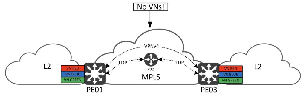
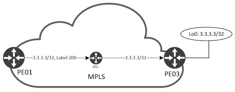
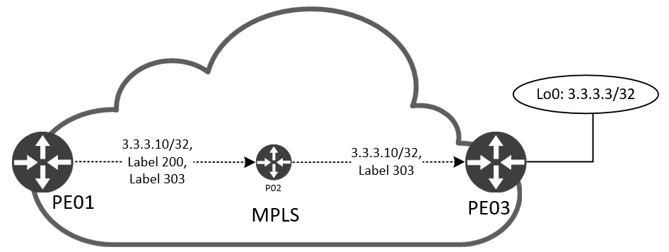
Before we dive into the realm of MPLS VPN’s bits and bytes I want to introduce the simple three node topology I’ll be using throughout the article:
If you are new to MPLS, here is some terminology:
- PE – Provider Edge router
- Interfaces with both the MPLS cloud and the regular segmented IP network. This node type connects to all MPLS node types.
- P – Provider router
- Internal to the MPLS cloud. This node connects to other P routers and PE routers.
- CE – Customer Edge router
- (not used in this post)
- Runs regular IP and resides outside the MPLS cloud. This node type connects only to PE nodes.
Since we want to segment our users using VNs we must configure VRFs on the PE nodes. In the topology I have three VRFs called RED, BLUE, and GREEN. Depending on the platform you’ll be able to have tens if not hundreds of VRFs deployed. Users in VN RED will not be able to reach users in VNs BLUE and GREEN.
In the middle we have a P router. I’ve added this node to the topology to be able to explain the process of label switching in the MPLS cloud, but also to illustrate how VRF-lite operates in a later section. We could have omitted this node and connected the two PEs back to back, but for the sake of understanding the technology it is there.
In the drawing more acronyms exist:
- VPNv4
- LDP
I will go over each of them as they are vital building blocks for a network providing MPLS VPN services.
IP reachability between MPLS nodes is mandatory, meaning we must have an IGP routing protocol configured between PE and P routers. In this case I’ve configured OSPF, but this could be any IGP.
Label Allocation, Distribution, and Forwarding
Before we can start switching packets using MPLS, we must allocate and distribute labels. A label header looks like this:
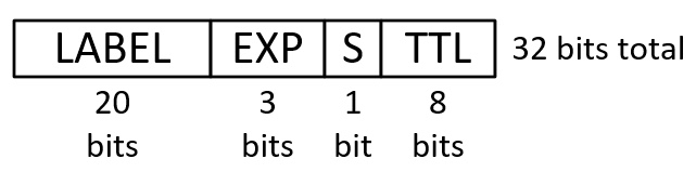
First we have the label itself. There can be approx 1 mio labels allocated (2^20 = 1,048,576). Next we have three bits for QoS markings called EXP, or experimental bits. A newer term for this is TC, or Traffic Class. The “S”-bit is referred to as “Bottom of Stack” and when set (1) it tells the router that this is the last label in the stack. More on this later. Finally to avoid endless looping of packets we have a TTL that decrements per hop just as we know it in IP.
Let’s focus on the P node in our topology for a bit. Now, since the MPLS cloud doesn’t know anything about the VNs, we need something other than an IP address to make our forwarding decisions on. This would be a label. In fact, we must have two labels in play for MPLS VPNs to work:
- Top label or transport label
- Used to forward traffic to a specific MPLS router
- Bottom label or VPN label
- Used to forward traffic to a specific prefix
Each label has its own function or meaning. Two different protocols are responsible for assigning and distribute these two labels:
- LDP (Label Distribution Protocol)
- Transport label
- BGP (Border Gateway Protocol)
- VPN label
We’ll start by looking at LDP. A router running LDP will allocate a label per (IGP) prefix it knows about. Since the transport label is used for the purpose of “reaching this router” and we can have multiple interfaces connecting to other P and PE nodes, we must have something unique to this router to be able to identify it to the MPLS network. For this we use a Loopback interface. For PE03 I have configured 3.3.3.3/32 on its Loopback0 interface:
! PE03
interface Loopback0
 ip address 3.3.3.3 255.255.255.255
LDP
Like BGP, LDP is a TCP-based protocol. It works a bit like an IGP with dynamic neighbor discovery and then builds a TCP session between the peers to exchange labels over:
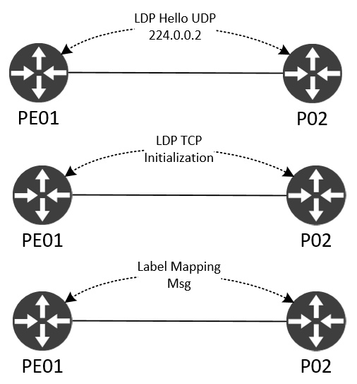
A Hello is sent out using the all routers multicast address 224.0.0.2 using UDP/646. When the LDP router sees another LDP speaker’s LDP Hello it starts a three-way TCP handshake and the LDP session can start initialization where stuff like version and timers are negotiated. Finally, the label exchange happens using Label Mapping Messages. If this process is successful between all MPLS nodes, end to end MPLS reachability has been achieved. This lays the base or foundation of any MPLS-enabled service, like L3 VPNs.
Most enterprises already run BGP in their network. So, in reality to use MPLS all you need to add to the network is LDP which is very easy to configure and implement. Have a look at the configuration needed to enable LDP on a router:
! PE01, P02, PE03
mpls ldp router-id Loopback0 force
!
router ospf 1
 mpls ldp autoconfig
The first command forces LDP router-id to be that of the Loopback0 interface. The second command is a shortcut for enabling LDP on all OSPF-enabled interfaces which is what we want. It is a great command, because when adding links we only need to worry about configuring OSPF. And we’re used to do that! Both commands are very template friendly.
With LDP sessions between PE01<->P02 and P02<->PE03 we can have a look at the labels used for P03 by PE01 and P02:
! PE01
PE01#sh ip cef 3.3.3.3/32
3.3.3.3/32
  nexthop 10.0.12.2 Ethernet0/0 label 200
PE01#
!
PE01#sh mpls forwarding 3.3.3.3
Local      Outgoing   Prefix           Bytes Label   Outgoing   Next Hop
Label      Label      or Tunnel Id     Switched      interface
101        200        3.3.3.3/32       0             Et0/0      10.0.12.2
PE01#

! P02
P02#sh ip cef 3.3.3.3/32
3.3.3.3/32
  nexthop 10.0.23.3 Ethernet0/1
P02#
!
P02#sh mpls forwarding 3.3.3.3
Local      Outgoing   Prefix           Bytes Label   Outgoing   Next Hop
Label      Label      or Tunnel Id     Switched      interface
200        Pop Label  3.3.3.3/32       18414         Et0/1      10.0.23.3
P02#
PE1 uses label 200 and sends the packet out its Eth0/0 interface to reach 3.3.3.3/32, the Loopback0 IP of PE03. P02 does not use any label to reach 3.3.3.3/32. This is not faulty, but merely an optimization. Because P02 is the last router before reaching PE03’s Loopback0 IP, we can safely remove (Pop) the label 200 and send the packet out Eth0/1 to PE03. This function comes in handy when we’re talking about MPLS VPNs. I’ll show it later. For now, to enforce the understanding of the above command outputs, let’s visualize first the label allocation done by LDP and second the label forwarding between the nodes.
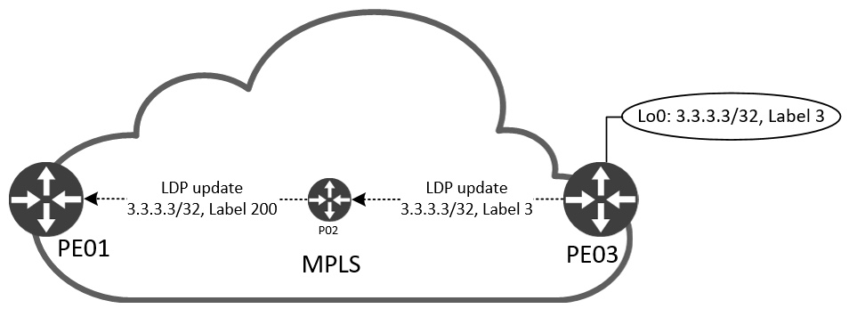
PE03 starts by advertising label 3 to P02 for its Loopback0 IP, 3.3.3.3/32. You might be wondering why we didn’t see label 3 in the Outgoing Label of P02 for 3.3.3.3/32. When PE03 sends label 3 to PE02 it tells P02 to remove (Pop) the packets received for 3.3.3.3/32 before sending them to PE03. P02 also allocates and advertises a label for 3.3.3.3/32 to PE01. This is shown in the Local Label of P02 and correspondingly as Outgoing Label on P01. Now, when PE01 sends traffic to 3.3.3.3/32, it adds the label 200 and forwards it to P02 that removes it and forwards it (with no label) to PE03:
We can even see this if we do a couple of captures when pinging between PE01 and PE03 Loopback0 interfaces.
This is taken on P02 Eth0/0 (facing PE01):
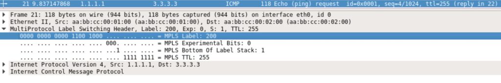
We see the label 200, EXP is 0, S-bit is 1 indicating that this is the last label, and a TTL of 255.
Packet as seen on PE03’s Eth0/0 (facing P02):
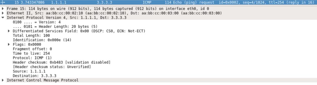
Notice that when the packet is received on PE03 it has no MPLS header. This is due to the pop action done on P02.
Now that we’ve established label switching between our MPLS nodes and understand LDP, we can have a look at BGP.
BGP
To get traffic from one endpoint to another, we must have two labels. LDP provides the transport (top) label and BGP is responsible for the VPN (bottom) label. This VPN label is what defines our VN prefix. In this network two Loopback10 interfaces have been configured in VN RED:
! PE01
interface Loopback10
 vrf forwarding red
 ip address 1.1.1.10 255.255.255.255

! PE03
interface Loopback10
 vrf forwarding red
 ip address 3.3.3.10 255.255.255.255
BGP has an address family for MPLS VPNs. This is called VPNv4 for IPv4. There is also one for IPv6 called VPNv6. Functionally there is no difference. We need a label for a prefix regardless of IP protocol version.
Since our P node doesn’t have any knowledge of VNs, it does not need to run BGP. Its job is to label switch packets using the top label – nothing else! We can even call it an LSR (Label Switch Router). This means that our PE nodes must receive VPNv4 updates. In this simple topology I’ve configured direct PE-to-PE BGP VPNv4 peerings:
 ! PE01
 router bgp 123
  bgp log-neighbor-changes
  no bgp default ipv4-unicast
  neighbor 3.3.3.3 remote-as 123
  neighbor 3.3.3.3 update-source Loopback0
  !
  address-family vpnv4
   neighbor 3.3.3.3 activate
   neighbor 3.3.3.3 send-community extended
  exit-address-family
  !
  address-family ipv4 vrf red
   redistribute connected
  exit-address-family

 ! PE03
 router bgp 123
  bgp log-neighbor-changes
  no bgp default ipv4-unicast
  neighbor 1.1.1.1 remote-as 123
  neighbor 1.1.1.1 update-source Loopback0
  !
  address-family vpnv4
   neighbor 1.1.1.1 activate
   neighbor 1.1.1.1 send-community extended
  exit-address-family
  !
  address-family ipv4 vrf red
   redistribute connected
  exit-address-family
In IOS when you configure a neighbor under the BGP process, the address family IPv4 unicast is automatically activated. I’ve disabled this using the no bgp default ipv4-unicast as we don’t need it for this topology. The peering between the PEs happen in the same AS, meaning that this is an iBGP (internal BGP) peering in VPNv4 address family. BGP packets are sourced from our Loopback0 interface which will also be used as the next hop for BGP VPNv4 updates sent between the peers. Finally, the neighbor send-community extended is needed to signal which VN membership the VPNv4 prefix belongs to. When you activate a neighbor under VPNv4, IOS automatically configures this for you. Neat!
Notice the address family ipv4 vrf red section. This is where we take in prefixes for BGP in VN RED. Specifically I’ve redistributed the connected prefixes – Loopback10.
Since we can have many VNs in a MPLS VPN network and this technology is also used to segregate companies or business units within companies and allows them to use a shared infrastructure (our MPLS cloud), it is possible to have overlapping IP addresses in the VNs. BGP VPNv4 makes this work using a route distinguisher (RD). Although this is a BGP feature, in IOS this RD is configured under the definition of the VRF:
! PE01
vrf definition red
 rd 1.1.1.1:10
 !
 address-family ipv4
  route-target export 123:10
  route-target import 123:10
 exit-address-family

! PE03
vrf definition red
 rd 3.3.3.3:10
 !
 address-family ipv4
  route-target export 123:10
  route-target import 123:10
 exit-address-family
In this example I’ve used the Loopback0 IP colon a number to configure the RD. For PE01 this value is 1.1.1.1:10 for VN RED. Each configured VN must have a per-VN unique RD. It is possible to configure the RD using a value of BGP ASN colon number instead. Pros and cons hereof is irrelevant to this post.
Within the VRF we also have something called route-targets, or RT. This value is configured using BGP ASN colon number, but could also be configured using an IP colon number just like the RD. Again, I’ll not discuss pros and cons hereof. What’s important to understand about the RT is that this number determines our policy for importing and exporting prefixes into and out of the VN! Let me illustration how this process works in conjunction with BGP VPNv4:
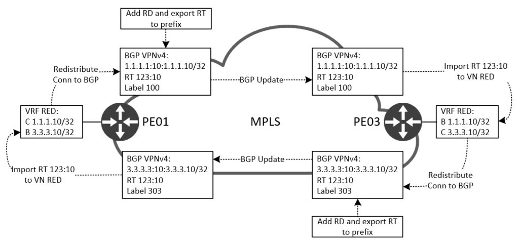
If we start by looking at PE03. Here we have a routing table for VN RED consisting of a connected (C) route for prefix 3.3.3.10/32. This prefix is redistributed into BGP as we saw in the BGP above configuration. When we do this, BGP will create a VPNv4 prefix which is made up of the RD colon prefix:
PE03#sh bgp vpnv4 u vrf red 3.3.3.10/32
BGP routing table entry for 3.3.3.3:10:3.3.3.10/32, version 2
Paths: (1 available, best #1, table red)
  Advertised to update-groups:
     1
  Refresh Epoch 1
  Local
    0.0.0.0 from 0.0.0.0 (3.3.3.3)
      Origin incomplete, metric 0, localpref 100, weight 32768, valid, sourced, best
      Extended Community: RT:123:10
      mpls labels in/out 303/nolabel(red)
      rx pathid: 0, tx pathid: 0x0
PE03#
Notice the first line reading 3.3.3.3:10:3.3.3.10/32 which is our VPNv4 prefix. Since each VN has its own RD the prefix 3.3.3.10/32 can be used in all VNs without colliding with each other. Also, look at the RT:123:10 which is our (export) route target configured under the VRF. Finally, we see a VPN label 303 which was added by BGP VPNv4. Now that the VPNv4 prefix has been created using the MPLS VPN building blocks needed, we can forward the update to the other PE, PE01. Here, the router will check the RT and import this prefix into its VN RED routing table. Also, the label 303 will be used by PE03 to make a forwarding decision when receiving a packet that has this label value.
Just like PE03 advertised a route for 3.3.3.10/32, PE01 will advertise its connected route in VN RED, 1.1.1.10/32, to PE03. Here the label 100 is used.
Here is a visualization of the label forwarding happening when PE01 sends traffic in VN RED to 3.3.3.10 “behind” PE03:
We can verify this by looking at CEF for VN RED at each hop:
! PE01
PE01#sh ip cef vrf red 3.3.3.10
3.3.3.10/32
  nexthop 10.0.12.2 Ethernet0/0 label 200 303
PE01#

! P02
P02#sh mpls forwarding-table labels 200
Local      Outgoing   Prefix           Bytes Label   Outgoing   Next Hop
Label      Label      or Tunnel Id     Switched      interface
200        Pop Label  3.3.3.3/32       1359          Et0/1      10.0.23.3
P02#

! PE03
PE03#sh mpls forwarding-table labels 303
Local      Outgoing   Prefix           Bytes Label   Outgoing   Next Hop
Label      Label      or Tunnel Id     Switched      interface
303        Pop Label  3.3.3.10/32[V]   0             aggregate/red
PE03#
!
PE03#sh ip cef vrf red 3.3.3.10
3.3.3.10/32
  receive for Loopback10
PE03#
At PE01, the ingress PE router, we look in the CEF table for VN RED and see a label stack consisting of two labels. The first, 200, is our transport label. The second, 303, is our VPN label. The packet is sent out Eth0/0 towards P02. Here a label lookup is performed (remember, that the P node makes forwarding decisions based on labels and not IPs). The label 200 must be removed from the stack and then forward the packet out Eth0/1 towards PE03, our egress PE. At PE03 the only label left in the packet is 303 which is allocated by PE03 itself, meaning it knows which prefix and VRF this label corresponds to and we can see that it is the receiving router for this prefix on its Loopback10 interface.
Let me show you the packet captures to solidify our understanding:
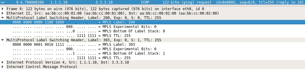
Taken ingress on P02 from PE01. Here we see our two label stack with the first (top/transport) label of 200. This is the label allocated and distributed by P02 to PE01 for reaching PE03’s Loopback0 IP. The bottom (VPN) label is 303 with the S-bit set (meaning last label).
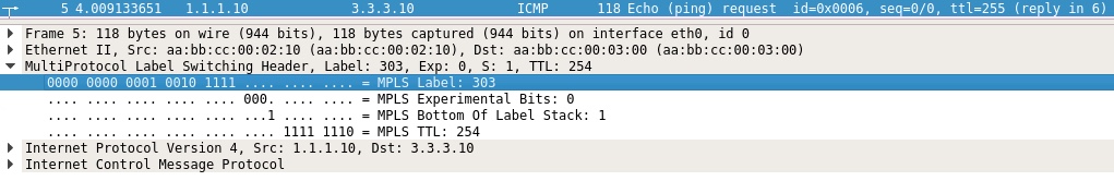
At PE03 we see that just one label exists in the packet. This is due to the fact that P02 Pops the top label (200) before forwarding the packet to the last hop router, or egress PE, PE03. This is an optimization that helps PE03 to only do one label lookup instead of two. Clever.
I haven’t shown you what the routing table looks like with MPLS VPNs, because the focus till this point was to explain the signalling and forwarding. Have a look at the routing table of PE01 for VN RED:
! PE01
PE01#sh ip route vrf red | be ^Gateway
Gateway of last resort is not set

      1.0.0.0/32 is subnetted, 1 subnets
C        1.1.1.10 is directly connected, Loopback10
      3.0.0.0/32 is subnetted, 1 subnets
B        3.3.3.10 [200/0] via 3.3.3.3, 02:02:04
PE01#
PE01#sh ip route vrf red 3.3.3.10

Routing Table: red
Routing entry for 3.3.3.10/32
  Known via "bgp 123", distance 200, metric 0, type internal
  Last update from 3.3.3.3 02:02:17 ago
  Routing Descriptor Blocks:
  * 3.3.3.3 (default), from 3.3.3.3, 02:02:17 ago
      Route metric is 0, traffic share count is 1
      AS Hops 0
      MPLS label: 303
      MPLS Flags: MPLS Required
PE01#
Notice the next hop of the BGP (B) learned route to 3.3.3.10/32. This is the IP of P03’s Loopback0 interface, or PE03’s BGP update source. This will be the case for any prefix in any VN that PE03 advertises reachability towards. By looking at our forwarding table, CEF, we resolve this next hop and take the label information along with an outgoing interface to see how the router actually forwards traffic to this destination.
By now you should have a good fundamental understanding of MPLS VPNs, its building blocks, headers, signalling, and forwarding mechanisms. I believe we can safely more on to talking about VRF-lite.
VRF-lite
The term VRF-lite simply means that we implement VRF-based segmentation in our network without using MPLS. With VRF-lite we no longer have the advantage of being able to abstract the inter-connection (cloud) between endpoint gateways (MPLS PE nodes) like we could with the MPLS example above. With this I mean that now we must configure VRFs at each hop between all our routers. This will add overhead to the manageability of the network, data plane, control plane, and hence affect scale. Let me demonstrate…
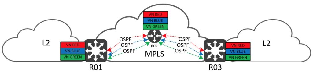
Since we have no protocol for differentiating between the VNs on the links between the routers, we must either add more physical links or implement another form of virtualization. It isn’t very feasible to just add more links, so let’s look at virtualizing the links we have to segregate the traffic. For this we use VLAN tags. VLANs will isolate the VNs from each other in the data plane, but we still must exchange routing information. A VRF-aware control plane protocol is needed per hop. In this example I use OSPF, but in theory it could be any routing protocol – including BGP.
Below is the configuration of VN RED with VRF-lite for all three routers.
! R01
vrf definition red
 !
 address-family ipv4
 exit-address-family
!
!
interface Ethernet0/0
 no ip address
!
interface Ethernet0/0.10
 encapsulation dot1Q 10
 vrf forwarding red
 ip address 10.10.12.1 255.255.255.0
 ip ospf network point-to-point
 ip ospf 10 area 0
!
interface Loopback10
 vrf forwarding red
 ip address 1.1.1.10 255.255.255.255
 ip ospf 10 area 0
!
router ospf 10 vrf red

! R02
vrf definition red
 !
 address-family ipv4
 exit-address-family
!
!
interface Ethernet0/0
 no ip address
!
interface Ethernet0/0.10
 encapsulation dot1Q 10
 vrf forwarding red
 ip address 10.10.12.2 255.255.255.0
 ip ospf network point-to-point
 ip ospf 10 area 0
!
interface Ethernet0/1
 no ip address
!
interface Ethernet0/1.11
 encapsulation dot1Q 11
 vrf forwarding red
 ip address 10.10.23.2 255.255.255.0
 ip ospf network point-to-point
 ip ospf 10 area 0
!
interface Loopback10
 vrf forwarding red
 ip address 2.2.2.10 255.255.255.255
 ip ospf 10 area 0
!
router ospf 10 vrf red

! R03
vrf definition red
 !
 address-family ipv4
 exit-address-family
!
!
interface Ethernet0/0
 no ip address
!
interface Ethernet0/0.11
 encapsulation dot1Q 11
 vrf forwarding red
 ip address 10.10.23.3 255.255.255.0
 ip ospf network point-to-point
 ip ospf 10 area 0
!
interface Loopback10
 vrf forwarding red
 ip address 3.3.3.10 255.255.255.255
 ip ospf 10 area 0
!
router ospf 10 vrf red
Now we must maintain a VLAN and IP Plan for all the VNs configured – for every L3 hop/router in the network! A new routing instance must be configured per VN, too.
Let’s quickly see the content of the routing table and forwarding table (CEF) of R01:
! R01
R01#sh ip route vrf red | be ^Gateway
Gateway of last resort is not set

      1.0.0.0/32 is subnetted, 1 subnets
C        1.1.1.10 is directly connected, Loopback10
      2.0.0.0/32 is subnetted, 1 subnets
O        2.2.2.10 [110/11] via 10.10.12.2, 00:26:53, Ethernet0/0.10
      3.0.0.0/32 is subnetted, 1 subnets
O        3.3.3.10 [110/21] via 10.10.12.2, 00:26:53, Ethernet0/0.10
      10.0.0.0/8 is variably subnetted, 3 subnets, 2 masks
C        10.10.12.0/24 is directly connected, Ethernet0/0.10
L        10.10.12.1/32 is directly connected, Ethernet0/0.10
O        10.10.23.0/24 [110/20] via 10.10.12.2, 00:26:53, Ethernet0/0.10
R01#
R01#sh ip cef vrf red 3.3.3.10
3.3.3.10/32
  nexthop 10.10.12.2 Ethernet0/0.10
R01#
As you can see the VRF-lite approach is very flat and therefore contains a lot of replicated configuration that we must document for every hop to be able to keep an overview of the network and to be able to troubleshoot it.
Conclusive MPLS VPN Comparison to VRF-lite
Try adding 10 or 20 VRFs to a network running VRF-lite, and you’ll start to see the burden laid upon both you and the network nodes.
I know the network would be more “simple” using VRF-lite, because we do not have the extra layer of labels involved. But whenever you expand the network, you must configure all the VNs on each link and node you add. And when you look at the next hop for a prefix in the routing table, this will be a per-VN next hop and not the BGP update-source.
The worst part of MPLS VPNs is to grasp the technology and its building blocks, which in reality is only LDP if you’re already familiar with BGP. We add just one protocol to the network and suddenly we can scale and remove lots of control plane state for the transit routers in our network. Provisioning a new VN is a matter of configuring just the PE nodes, meaning we do not risk mis-configuring our important P nodes, or if no P nodes are present, we need not configure anything between the PE nodes – BGP ensures that the new VN and its prefixes are dynamically allocated the necessary labels to be able to forward traffic on the existing links in our MPLS cloud. This approach really cuts down on the configuration and manageability overhead required to deploy and maintain such a network.
In my opinion the advantages of using MPLS far outweigh the simplicity of using VRF-lite. And now that you know how MPLS VPNs work, I sincerely hope you’ll have no fear of trying it out and even consider implementing it in your network – if applicable.
Thank you for reading this post. I hope you enjoyed it.
Om forfatteren


Relateret