Blog
DNAC LAN Automation vs. PnP
The Challenge Operating a network can be a daunting task. Especially when you find yourself manually repeating ordinary work on a regular basis. As a network engineer you are likely to enjoy challenges with protocols and designs rather than unboxing, mounting, and installing hardware. The time spent on this everyday work should be kept at […]

The Challenge
Operating a network can be a daunting task. Especially when you find yourself manually repeating ordinary work on a regular basis. As a network engineer you are likely to enjoy challenges with protocols and designs rather than unboxing, mounting, and installing hardware. The time spent on this everyday work should be kept at a minimum. In a streamlined network design, the configuration of new equipment should be based on a template with few variables, such as hostname and IP addressing. Many companies already practice using templates, but for the most part the engineer must still manually adjust these variables, or at best some advanced excel spreadsheet or flat text file is used with a manual search and replace to build new configurations. Next, the device is powered up, connected to with a console cable and the newly build configuration is pasted into the device before installing it in its final location. Oh, and now both software upgrade and licensing tasks must be performed to be compliant. The workflow is manual, time consuming, and worst of all error prone due to the inevitable human factor.
Introduction
Companies seek ways to eliminate manual intervention when it comes to network operations. It brings great value to a business to be able to automate as many repeating tasks as possible. At a minimum to provide a solution that minimizes time spent on these tasks while ensuring a consistent outcome – every time. This should help lower OPEX. Cisco DNA Center is a product that offers such a solution. In particular the automation of onboarding of new devices for the purpose of either bringing up a new network or expand an existing network, is addressed in the following sections.
LAN Automation
DNA Center features LAN automation which can build the underlay used for an SD-Access deployment – or if you simply want a quick way to build a routed network using ISIS. The general idea is to leverage PnP to bring up a routed network – automated by DNAC. The user need not think about or have any experience with configuring routing protocols, or how PnP works. In a few steps an entire network can be provisioned in very little time. Minutes.
Below topology is used to demonstrate how LAN automation works.

Some restrictions and limitations exist for LAN automation:
- Seed device cannot be an SVL device
- No support for stack renumbering
- No image upgrade of the devices
Whenever using PnP we must have a way to provide IP reachability for DNAC. Besides IP connectivity, the PnP device must also know how to contact DNAC for onboarding. More information about PnP can be found here
Luckily LAN automation automates this configuration for us using an IP pool of type “LAN”:

This IP pool is used by DNAC for the following functions:
- Temporary DHCP server
- ¼ of the IP pool is allocated for DHCP
- IP pool must be between /23 and /25 (inclusive)
- Linknets for P2P links
- With DNAC 2.1.2.5 these are configured as /31s
- Loopback addresses for management of the nodes and SDA fabric operation (LISP RLOC and VXLAN VTEP)
You still need to configure and add a seed device for DNAC. On this device, DNAC will configure the DHCP pool and routing. I’ve configured BGP for initial reachability between my fusion switch and the border node which will act as my seed device. BGP is needed for SDA on the border for L3 handoff anyways. Note that the IP address of the seed device will be in a different IP subnet than the LAN automation IP pool. If you want a very strict IP addressing plan with all loopbacks in a site belonging to the same subnet allocation, you must either use regular PnP, or manually change it once LAN automation is complete.
I’ve configured this on the border (seed):
router bgp 65001 bgp log-neighbor-changes neighbor 100.64.1.249 remote-as 65000 ! address-family ipv4 This will ensure that when DNAC configures VLAN1 for 100.64.0.0/25 it will be redistributed (connected) and when it finishes with ISIS, this too will be redistributed. This is a must to ensure reachability during and after LAN automation.
To see what happens on my seed device during LAN automation, I’ve configured this:
event manager applet catchall event cli pattern ".*" sync no skip no action 1 syslog msg "$_cli_msg"The EEM applet will log any command entered to the device. Here is an example:
border#sh run int lo0 Building configuration... Current configuration : 68 bytes ! interface Loopback0 ip address 100.64.1.254 255.255.255.255 end border# *Jan 30 15:28:48.690: %HA_EM-6-LOG: catchall: show running-config interface Loopback0 border#Start LAN automation
Below are my settings for starting LAN automation:


The primary device (seed) is our pre-configured border and its downstream ports (where the edge nodes connect). The LAN pool is selected along with an ISIS domain password and a hostname prefix for our edge nodes.
Here is the log with the output of what DNAC does to the seed device upon starting LAN automation:
Highlights are:
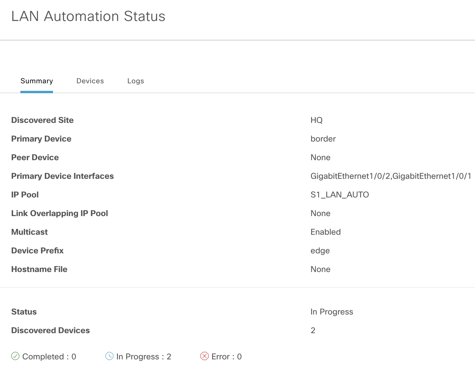
! MTU system mtu 9100 ! Multicast ip multicast-routing ip pim ssm default ! interface Loopback0 ip pim sparse-mode ! interface Loopback60000 ip address 100.64.0.33 255.255.255.255 ip pim sparse-mode ! ip pim rp-address 100.64.0.33 ip pim register-source Loopback0 ! ISIS router isis net 49.0000.1000.6400.1254.00 domain-password zartmann metric-style wide nsf ietf log-adjacency-changes bfd all-interfaces passive-interface Loopback0 default-information originate ! interface Loopback0 ip router isis clns mtu 1400 ! interface Loopback60000 ip router isis ! DHCP ip dhcp excluded-address 100.64.0.1 ! ip dhcp pool nw_orchestration_pool network 100.64.0.0 255.255.255.224 option 43 ascii 5A1D;B2;K4;I10.181.15.10;J80; default-router 100.64.0.1 class ciscopnp address range 100.64.0.2 100.64.0.30 ! ip dhcp class ciscopnp option 60 ^ciscopnp ! VLAN1 interface Vlan1 ip address 100.64.0.1 255.255.255.224 no shutdown ip router isis clns mtu 1400 bfd interval 500 min_rx 500 multiplier 3 no ip redirectsNow the seed device is ready to onboard the edge nodes. Here are some screenshots to verify the progress:
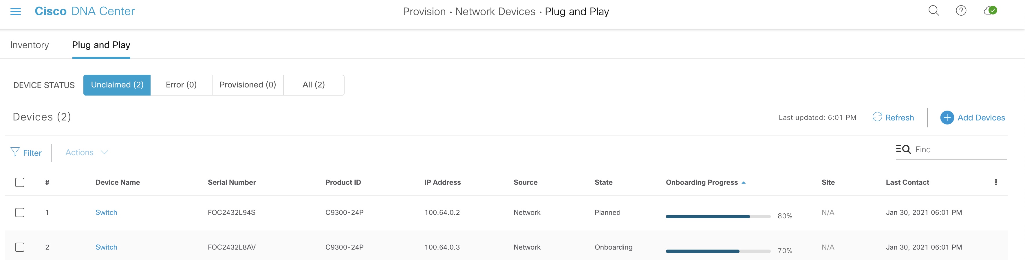
We can see that LAN automation in fact uses PnP to onboard devices.
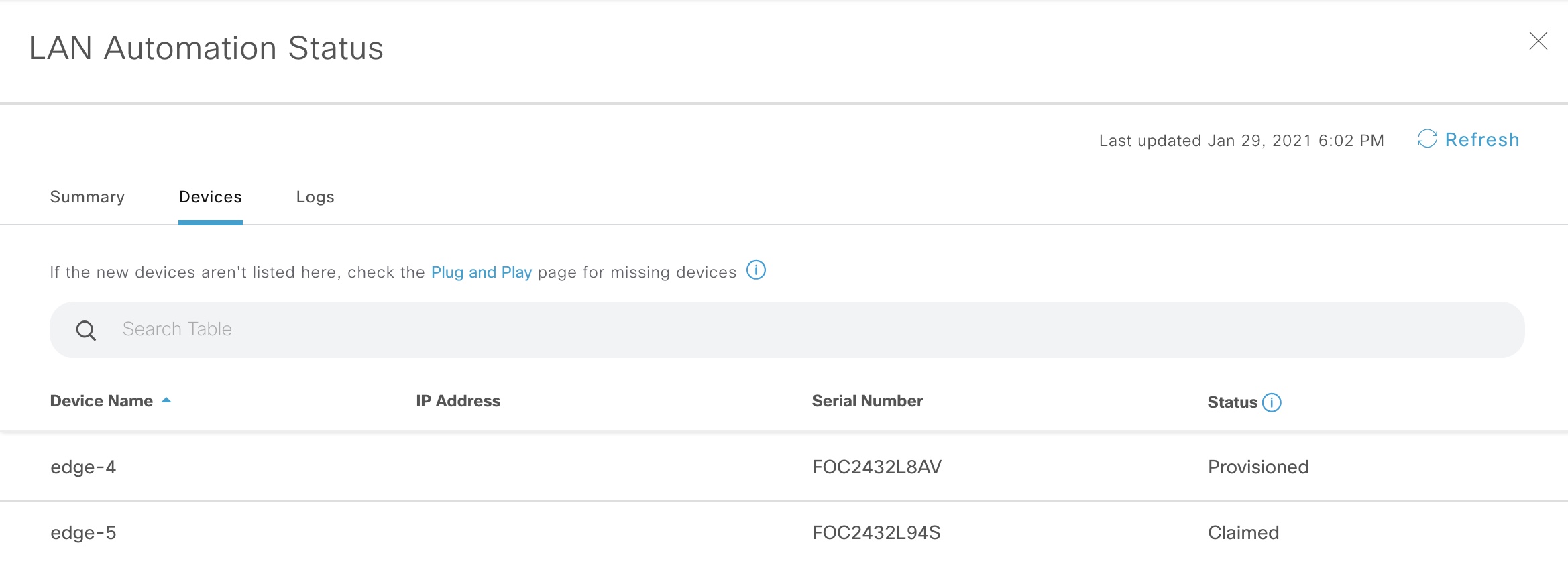
Once devices have been claimed and onboarded, the state of LAN automation changes to “Completed”. Now it is safe to stop LAN automation, and this is what happens to our seed device:
border_seed_completed_stop
Highlights for the stop process:
EEM to configure downlinks (only Gi1/0/2 shown) event manager applet _L3Applet_GigabitEthernet1/0/2 authorization bypass event timer countdown time 1 action 1.0 cli command "enable" action 1.1 cli command "config t" action 1.2 cli command "interface GigabitEthernet1/0/2" action 1.3 cli command "no switchport" action 1.4 cli command "ip address 100.64.0.38 255.255.255.254" action 1.5 cli command "ip router isis" action 1.6 cli command "isis network point-to-point" action 1.7 cli command "no shutdown" action 1.8 cli command "bfd interval 100 min_rx 100 multiplier 3" action 1.9 cli command "no ip redirects" action 2.0 cli command "dampening" action 2.1 cli command "logging event link-status" action 2.2 cli command "load-interval 30" action 2.3 cli command "description Fabric Physical Link" action 2.6 cli command "clns mtu 1400" action 2.7 cli command "exit" action 2.8 cli command "no event manager applet _L3Applet_GigabitEthernet1/0/2 authorization bypass" action 4.1 cli command "interface GigabitEthernet1/0/2" action 4.2 cli command "ip pim sparse-mode" action 4.4 cli command "do write memory" action 4.5 cli command "end" action 4.6 cli command "exit" ! VLAN1 interface Vlan1 no ip router isis no clns mtu no ip address no bfd interval ip redirects ! DHCP no ip dhcp pool nw_orchestration_pool no ip dhcp excluded-address 100.64.0.1 no ip dhcp class ciscopnpThe magic of converting VLAN1 to routed links is done using an EEM applet.
That is how LAN automation works. You might discuss the un-modifiable configuration template that DNAC uses. Especially its ISIS configuration that features legacy clear text authentication and the fact that it configures L1L2 routing. Also, no protocol tweaking is done in terms of lsp and spf optimizations that you usually do with ISIS. But, if the case is to just create a routed network in an automated way with no knowledge, LAN automation does it for you.
PnP
Compared to LAN automation, PnP gives you complete control of the configuration via the template you provide. Also, PnP has these advantages over LAN automation:
- Stack renumbering capability
- Image upgrade during PnP
On the other hand, you’ll not be able to provision a three-tier network in one go with PnP. This LAN automation supports due to its clever EEM applet that finishes the PnP process off by migrating VLAN1 to routed links.
To return to the ISIS configuration that LAN automation does. Here is the template I usually use for ISIS:
key chain isis-keys key 1 key-string zartmann ! interface Loopback0 ip address 100.127.127.1 255.255.255.255 ! router isis 1 net 49.0001.1001.2712.7001.00 is-type level-2-only authentication mode md5 authentication key-chain isis-keys metric-style wide max-lsp-lifetime 65535 lsp-refresh-interval 65000 spf-interval 5 1 20 prc-interval 5 1 20 lsp-gen-interval 5 1 20 no hello padding nsf ietf bfd all-interfaces log-adjacency-changes passive-interface Loopback0 ! interface Gi1/1/1 ip address 100.126.1.1 255.255.255.254 isis network point-to-point isis metric 40 level-2 isis authentication mode md5 isis authentication key-chain isis-keys ip router isis 1With the above configuration we have an optimal ISIS configuration in terms of lsp and sfp tuning. Also, it is more secure with MD5 type passwords for both IIHs and LSPs. My template configured the router as a L2 IS. There is no need to have both L1 and L2 adjacencies.
Offbox Automation
Rich APIs make it possible to interact with DNAC. You can script your templates and use APIs to send it to DNAC and create a planned PnP task containing necessary information such as hostname, serial number, stack renumbering, and software version required for the device along with its placement in the site hierarchy after successful onboarding. This is the way to go if bringing up new devices happens on a regular basis, or you want to be able to do bulk provisioning of new sites with many devices.
DNAC itself has a template editor which now features Jinja2. A tempate language with dynamic capabilities to bring intelligence to your configurations.
Conclusion
With DNAC it is now possible to create an automated routed network in minutes – not hours. No knowledge of how to configure routing protocols is needed. LAN automation can be used to bring up a routed network. The feature is intended for provisioning an underlay network for SD-Access, but can be used just to create a routed network. Some limitations exist with LAN automation, but it is an easy way to start an SD-Access implementation.
If custom configurations are required, or you simply do not need a routed network, but just want to be able to add devices to your network, Cisco PnP can be used. Here you have full control over the configuration and even the ability to upgrade software and renumber a stack during onboarding.
Offbox automation can be used with DNAC’s APIs which will use DNAC as an engine towards the network.
There is no longer a reason to manually configure new devices using a console cable. A method that belongs in the past. The future relies on automation which DNAC provides for us. And device onboarding is just one of its use cases.
References
- SVL support – CSCvs99008
- LAN Automation: Step-by-step deployment guide and Troubleshooting
- Cisco DNA Center SD-Access LAN Automation Deployment Guide
- LAN Automation Tips and Tricks for Digital Network Architecture (DNA) Center
- Configuring IS-IS Authentication
- Adam Radford – Cisco Blogs
- Jinja2 – Cisco Blogs
Om forfatteren


Relateret