Whitepaper
How to Segment your Industrial Network – a practical methodology!
The trend toward environments where IT (Informational Technology) and OT (Operational-Technology) networks converge offers great opportunities and is a vital part of enabling Industry 4.0 with a greater degree of connectivity and data collection. If interested, go to the related blog post ‘First steps toward ICS/OT Security written by our Cybersecurity Analyst, Danijel Grah. At […]

The trend toward environments where IT (Informational Technology) and OT (Operational-Technology) networks converge offers great opportunities and is a vital part of enabling Industry 4.0 with a greater degree of connectivity and data collection.
If interested, go to the related blog post ‘First steps toward ICS/OT Security written by our Cybersecurity Analyst, Danijel Grah.
At the same time, the connection involves entirely new exposures of risks and threats to OT networks which have traditionally been very isolated networks. OT networks are an extremely vulnerable environment, with many particularly vulnerable systems with old operating systems that are no longer maintained or not even at all updated with patches and updates!
The vulnerabilities of the OT systems can significantly increase the risk of industrial espionage and sabotage in organizations and critical infrastructure.
Due to the nature of the OT networks, OT security has never been a focus area, all focus has been on keeping the network up and running. In general, as few changes as possible in these networks are preferred to minimize production outages.
Network Segmentation
By dividing the network into multiple logical networks and restricting access between them, we limit the attack area which a single system can reach. An accepted reference model for making this division is the Purdue reference model (PERA). Purdue isn’t new, it was developed during the late 1980s. Purdue has since then been further developed, updated, and has influenced subsequent standards such as ANSI/ISA95/99 and IEC 62443.
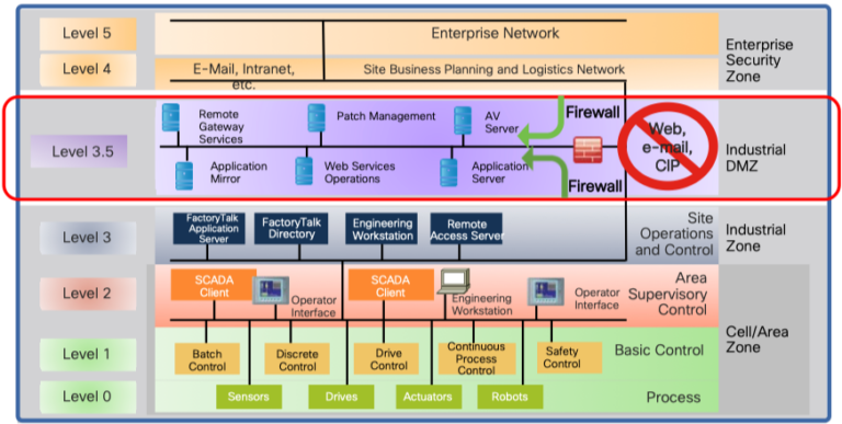
Level 0-2 – Defines the physical cell. Here we find units such as PLCs, HMI, controllers, and workstations.
Level 3 – Production system – Manages the production workflow to produce the desired products.
Level 4-5 – IT network. Here we find systems such as business logistics systems, external WAN connections, Internet connection, and more.
In the Purdue model, a cell is defined as a functional area (production line) within a production facility. Many factories have multiple cells, up to hundreds.
Based on the Purdue model, we introduce three important concepts for building a secure OT network:
- A clear demarcation between IT (Level 4-5) and OT (Level 0-3) by introducing a DMZ zone called Industrial-DMZ (IDMZ). The purpose of this IDMZ zone is to break direct communication between the IT and OT zones by placing proxy services, jump servers, and any other resources directly in this zone. This prevents outbreaks in the IT environment to enter the OT zone at all. Most attacks originate in the IT zone as it is Internet-connected and generally far more uncontrolled.
- Logical segmentation between cells in the production zones of the OT network (zone 0-1).
- A capability to allow network access for external suppliers in a controlled and restricted way to the OT network and only provide them access to the system they need to reach.
Traditionally, network segmentation is performed by separating different subnets from each other through mechanisms that open and close IP addresses and ports. It’s a rather big challenge in an OT environment since such a logical division would require that all IP addresses on all endpoints are changed. Introducing segmentation is extremely complicated and the necessary changes has a very big impact on the network (also in the event of a rollback). Another important aspect is that a traditional division of OT units into different networks usually takes place with manual switch-unique configuration. In most organizations, this means that every single change requires the efforts of the network administrators who often work in another department.
The methodology advocated in this whitepaper offers an alternative solution that can offer full network segmentation of the cells without the OT endpoints needing new configurations (they can retain existing IP addressing) and where all configuration in the switches is completely dynamic where correct network access follows the connecting resource. This greatly facilitates a migration and rollback as OT staff can complete the entire migration and mapping of endpoints on their own without involving the network people.
Network segmentation with Cisco TrustSec
Cisco TrustSec is a collection of security technologies from Cisco. TrustSec provides software-defined network segmentation to protect business-critical assets. Cisco TrustSec segmentation is easier to enable in an industrial network than traditional VLAN-based segmentation because it only works on layer 2 and is IP address independent in layer 3. The clients on the network are assigned an SGT tag, and this tag is carried in the Ethernet frames themselves.
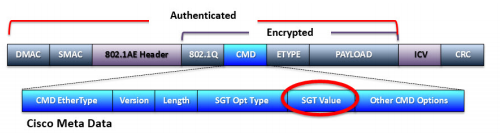
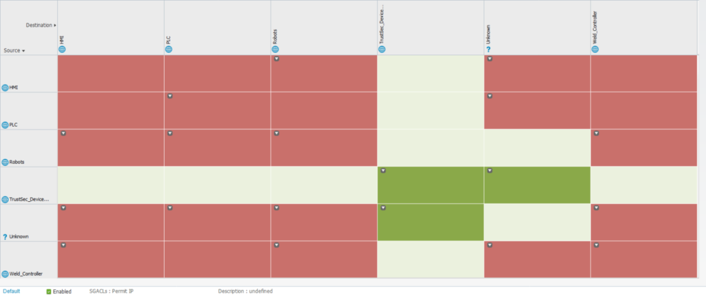
A user or client can be assigned an SGT via 802.1X (dynamic) or static (via static switch configuration, per port or per VLAN). In order to control which endpoints can communicate with others, an SGACL is centrally defined which all switches will enforce their behavior on. An SGACL is a full matrix of our defined SGT tags. This matrix determines whether traffic should be allowed between two unique SGTs (or to and from the very same SGT). This enables us to let two different cells share layer 2 addresses (VLAN) and layer 3 addresses (subnet), and we can still achieve network isolation by preventing communication between the tags we assign to the cells in the SGACL matrix. Of course, it is also possible to do the same thing even though the devices are on different networks if desired.
The Cisco Identity Services Engine (ISE) platform is the feature that provides identity-based access control, context, and visibility (for example, user, device, location, and time) for the devices and users connected to the network. Cisco ISE is also a controller and orchestrator of TrustSec-based software segmentation policies and is responsible for defining and distributing SGACL to the network devices.

Let OT and IT play together safely – and gain insight into production
IT is crucial for a company’s operations and the ability to gain insights intoLearn about OT Security Best Practices and how Cisco Cyber Vision can provide an overview of OT devices in operation and m…
About the author

Andreas di Zazzo
Senior Network Architect and double CCIE at Conscia Sweden
Andreas di Zazzo; 2x CCIE # 28735, is a Senior Network Architect at Conscia Sweden and works as a trusted advisor to large organizations in networks and security. His areas of expertise include IoT, LAN and Wi-Fi solutions based primarily on Cisco solutions. An area of expertise is precisely network authentication using 802.1X and related technologies.


Related